An Innovative Approach for a Compact, TV-centric Audio System
Based on the miniDSP Flex and Device Console
You can create a compact home theater using an innovative approach to build a high fidelity 3.1 stereo system that adds depth and dynamic realism to the home movie experience. This TV-centric design uses a miniDSP Flex with Device Console to create an enjoyable and dimensional listening experience.
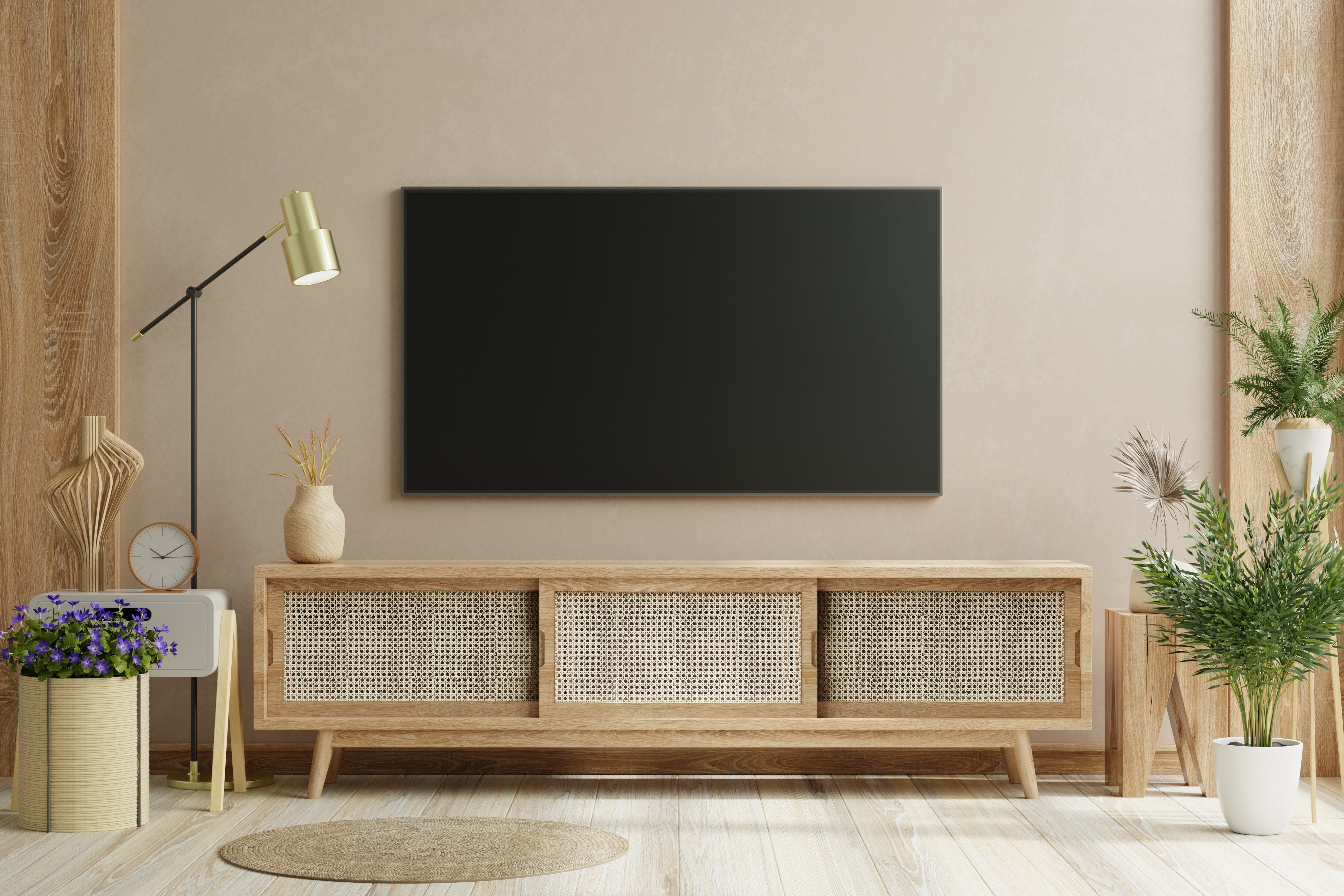
With the development of advanced performance in compact speakers and subwoofers, high impact, high fidelity sound is now attainable in a much smaller space. When building a TV-centric audio system the components can be housed in a single TV cabinet for a space-saving profile (subwoofer off to the side).
How does it work?
The design concept is TV-centric, with sources connected to your TV by Wi-Fi, LAN or HDMI. These sources can include Apple TV, a Blu-ray disc player, cable modem, Xbox or others. The TV then routes digital audio via TOSLINK fiber optic (PCM Stereo) to a miniDSP Flex.

The Flex serves as the system's processor, incorporating the main left, main right, center channel and subwoofer. The system features a simple TV-centric user interface, giving the user full control over audio signal routing, levels and crossovers for main left, main right, center and subwoofer channels.
This approach does not use an audio-video receiver (AVR) or rear surround speakers and does not support home theater decoding / standards such as: Dolby™, DTS, THX, etc.
How do you build the system?
From the TV, high definition audio is output in PCM digital audio over TOSLINK (fiber optic) into the miniDSP Flex. This provides a pure digital stereo signal that is then processed into the 3.1 channels.
System Interconnect Diagram

Referring to the diagram above, be sure to verify your connections as follows:
- TOSLINK from TV to Flex
- RCA cable from Flex to subwoofer
- RCA cables from Flex to three-channel amplifier
- Speaker wire connections from three-channel amplifier to left, right and center speakers
Once you've completed the physical setup of your TV-centric system, the next step is to finalize the miniDSP Flex configuration using Device Console.
How do you complete the system setup?
After all the physical connections are made, you’ll use the Flex and Device Console to provide control access to:
- Routing Matrix
- Crossover Frequencies
- Channel Levels
- Parametric equalization (PEQ)
The routing matrix in Diagram 3 shows how the center channel and subwoofer channel have been monauralized. By combining the left and right channels into one, the resulting monauralized channel creates a simple home theater listening environment.
The channel gain is used to adjust the left, right, center and subwoofer loudness to give the most balanced listening experience. It is possible to set up to four different preset configurations, so you can have dedicated presets for movie night and high-definition audio listening.

Signal Routing
Set the routing matrix on the input page of Device Console as follows:
- Output channels 1 and 2 for the stereo left and right
- Channel 3 for the monauralized center channel
- Channel 4 for the monauralized subwoofer

System Crossovers
Effective crossovers between the main and center speakers and subwoofer follow typical audio video standards.
The center channel speaker has a frequency range chosen primarily for voice. In this example, we have chosen 340 Hz to 4,000 Hz with 12dB per octave slopes. With experimentation, listening and measurement you can find the crossover frequencies that are most pleasing to you.

In addition to the center channel tuned to enhance voice, you can see the crossover at 80 Hz is separating the subwoofer from the left and right main full-range speakers.
, center speaker and subwoofer.")
Verifying Polarities
You can verify polarities using REW and the invert feature on the miniDSP Device Console. Simply invert any of the full-range speakers or subwoofers relative to one another to confirm polarity.
The example below shows inverting the subwoofer, which reveals a significant dip around the crossover frequency. The same thing can be done with the main and center speakers to determine if they are subtracting or adding to one another. The polarity is correct when the channel levels are additive.

Setting Speaker Levels
The next step is to adjust the relative levels of all speakers and subwoofers using REW and a miniDSP UMIK-1. From the central listening area, adjust the levels to be close and especially to provide the most enjoyable listening experience. You can increase the accuracy of this measurement by moving the microphone around to several locations within your listening space and averaging the results.

In this 3.1 setup example, we show a slightly elevated subwoofer level and a slightly elevated center channel level (for voice). The most effective way to do this is to make adjustments for the best listening experience then verify what you're hearing with REW measurements.

What about room correction?
There are several options when it comes to tuning your system with room correction.
- Dirac Live solution providing state-of-the-art frequency and time domain room correction
- Basic solution with tuning to taste using the parametric equalizer in the miniDSP Flex
- Room EQ Wizard (REW) solution to create equalization correction filters, see: REW EQ Window
Before you begin your system / room correction project, complete all of the basic setup steps in the above sections. Then do some serious listening to make sure you're pleased with the preliminary results. It’s key to have a proper sounding system to provide the basis for successfully completing a room correction project. Check out our tech blog Using Key Measurements to Verify Basic System Setup or see the Additional Technical Resources section below.
Dirac Live Solution
This is a brief outline of the Dirac Live process. Please refer to the Dirac Live User Manual for a detailed description of the procedure.
- Create a Dirac Live account and download Dirac Live
- Verify you have all the proper USB connections in place, with adequate room to see your computer and be able to fully move the microphone around the measuring area
- Initiate Dirac Live from the miniDSP Device Console
- Confirm that you are logged into your Dirac Live account
- Perform Dirac Live level calibration
- Select the focus listening area size
- Perform all specified measurements
- Proceed to Dirac Live correction waveform creation
- Export the Dirac Live project to any miniDSP preset
- Save your Dirac Live project

Tuning to Taste with Parametric Equalization - Basic Solution
You can tune to taste by adding parametric equalization (PEQ) curves at any time. These are applied on the Device Console output parametric equalization page and are created individually for each output channel: left, right, center and subwoofer.
The ease of adding different PEQ curves tuned to your listening preferences makes the system flexible and fun. In the example below, we show a Fletcher-Munson curve that was generated using the miniDSP Flex parametric equalizer.

How do you use the system?
Once the system is set up, it is simple for the entire family to use.
Modern televisions are equipped to accept a variety of high performance digital video and audio sources that are easily selected from the TV's remote. Simply use the remote to select the input desired.
System volume is controlled with the miniDSP Flex’s IR remote or volume knob.
If you have questions or would like to discuss in more depth, feel free to give us a call or drop a line.
Share: