How Do I Convert a DTS or Dolby Digital Bitstream
for My 3.1 Home Theater System Without Losing Any Audio Detail?
Using a miniDSP Flex HT, you can create a decoded 3.1 AV system by converting the DTS or Dolby input. The key to success is the proper downmixing of the 7.1 channel content to 3.1.
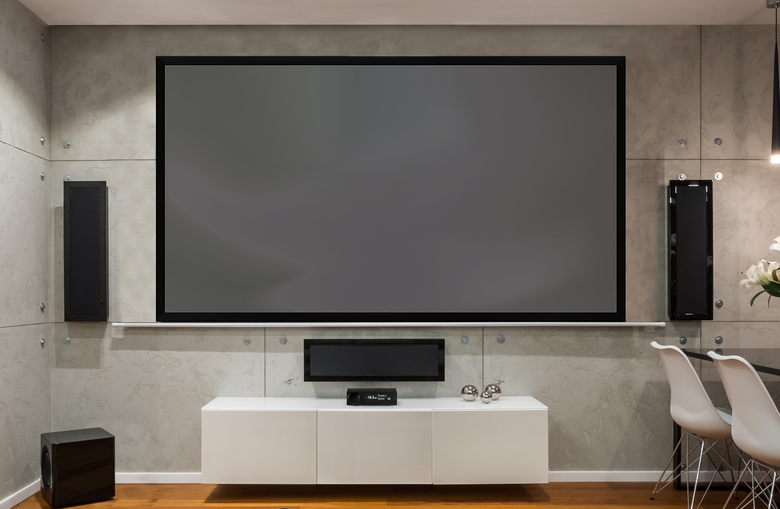
Our example is for a TV-centric audio system with a compact profile that provides high fidelity sound for smaller spaces, or where room aesthetics take precedence. If your stereo system is already set up with a TV, or you are planning to add a TV to your listening space, then this solution is an easy and non-intrusive choice. It also reduces the need to route cables or install speakers on the rear and side walls.

Contents
- System Design Concept
- System Block Diagram
- Signal Flow Diagram
- Configuring Device Console
- Bass Management Page
- Channel Routing Page
- Output Channels Page
- Room Correction Using Dirac Live or REW AutoEQ
- Signal Flow Diagram Template
1. System Design Concept
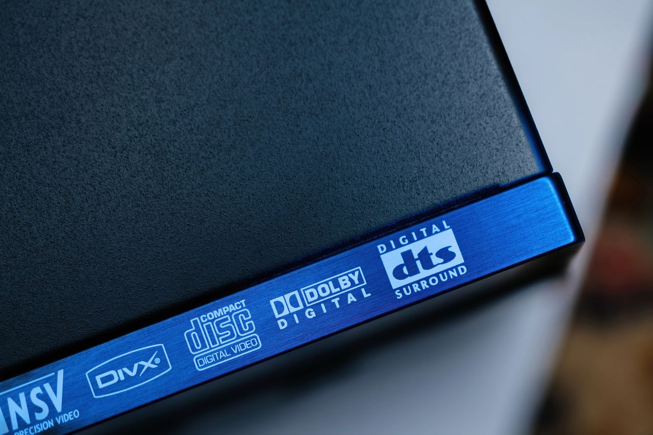
It’s critical that the incoming DTS or Dolby bitstream is properly converted for a 3.1 layout. To accomplish this, the surround channels are routed back into the main channels and the LFE channel is combined with low frequencies from other channels.
This method uses sources that can decode DTS and Dolby into linear pulse code modulation, or LPCM, and are connected to the TV. Devices that can decode the bitstream include Apple TV, Lumin, Roku and Oppo.
In our example using Apple TV, we send the decoded LPCM to a smart TV. The TV then passes the LPCM via eARC to the miniDSP Flex HT. From here the Flex HT downmixes all of the audio content into 3.1 channels that are then sent to the amplifiers, speakers and subwoofers.

If your setup does not convert bitstream audio into LPCM, then you can use an adapter such as the OREI HDA-934, which converts DTS or Dolby Digital into eARC LPCM.

2. System Block Diagram
The system wiring is completed as follows:
- eARC from TV or HDMI processor to Flex HT
- RCA cable from Flex HT to subwoofer
- RCA cables from Flex HT to three amplifier channels
- Speaker wire connections from the amplifiers to left, right and center speakers

3. Signal Flow Diagram
The down conversion from 7.1 to 3.1 on the Flex HT is a matrix-based process. This is illustrated in the Signal Flow Diagram and incorporates the following:
- Front left and right channels receive their own signal
- Surround and rear channels are then mixed into the front channels
- The center channel is passed through
- The subwoofer channel is composed of the low frequencies from the main left and right, LFE and center channels, which are then routed to the subwoofer output

4. Configuring Device Console
Device Console is the user interface that allows you to configure the setup pages in the Flex HT, including:
- Signal Routing
- Crossover Frequencies
- Relative Levels
- Parametric Equalization (PEQ) and/or Dirac Live
4a. Bass Management Page
In this example we use the Bass Management and Channel Routing pages to downmix the 7.1 channel content to 3.1 content in a way that preserves all of the audio details.
The signals are combined and routed to their respective speakers, as shown in the following diagrams.
Note that we have added 10 dB to the LFE input channel, which is required due to the 10 dB of attenuation that occurs in the AV mastering process.

Here’s a more detailed view of the signal flow diagram that focuses on the bass management page.

4b. Channel Routing Page
On the Channel Routing page we are mixing and splitting the default 7.1 channels coming in over HDMI eARC to match the requirements of our 3.1 system.
The surround and rear channels are attenuated by 3 dB and then mixed into the front left and right channels. This attenuation prevents the surround content from overwhelming the front main content.

4c. Output Channels Page
The Output Channels page allows you to modify the signals being sent to the speakers and subwoofers. This is where you’ll set individual channel parameters for proper, balanced sound with clear voices and tight powerful bass. These critical settings are completed prior to final room correction, and include:
- Gain
- Crossover
- Delay
- Inversion

For more information on how to finetune the Output Channels page, please check out these videos on our YouTube channel:
- Overview of miniDSP Device Console
- Using miniDSP Device Console and REW to Verify Basic System Setup
5. Room Correction Using Dirac Live or REW AutoEQ
Dirac Live and REW AutoEQ are the best options when it comes to your room correction project.
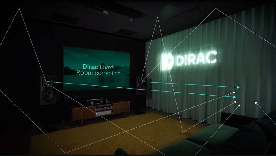
Dirac Live
Dirac Live is a powerful, high performance room correction algorithm that operates in both the time and frequency domain. A Dirac project is performed after all of the other system setups have been completed and verified.
Please refer to the section on Configuring Dirac Live in the Flex HT User Guide for details.
When Dirac calibrates, it will lower the level of the subwoofer channel(s) to match the speakers. As this is not a desired result, use the following steps to avoid the issue:
Step 1. On the Output Page, reduce the subwoofer channel by 10 dB
Step 2. Run your Dirac Live project
Step 3. Increase the subwoofer channel by 10 dB
Step 4. Confirm the levels are as expected by running a measurement with REW
Once your Dirac project is complete and you have added 10 dB back to the subwoofer channel, the graph will look like this. You can see the frequency response curves are much flatter and smoother.

REW AutoEQ
The optional REW AutoEQ feature provides a simplified measurement and equalization tool for users to gain quick room correction results.
REW AutoEQ is launched from within the relevant PEQ block in Device Console. When AutoEQ is performed, REW calculates a correction EQ based on the measurement and displays the result.

6. Signal Flow Diagram Template
Using a Signal Flow Diagram, you can easily plan your system layout before actual implementation. It also helps you spot potential problems and work through solutions. You can download a blank Signal Flow Diagram here.

Check out the companion video and more on our YouTube Channel
https://www.youtube.com/@deer_creek_audio
If you have questions or would like to discuss in more depth, feel free to give us a call or drop a line.
Share: