Using miniDSP Device Console to Add
Precise, Deep Bass to Your Home Theater Sound
Looking for accurate, ultra-deep bass in your home theater? Do you want to optimize your sound system by adding multiple subwoofers? In this blog we will help you do just that by walking through the process of setting up a multi-subwoofer configuration for a home theater using miniDSP Device Console and a 2x4 HD or Flex.
Contents
- System Architecture Concept
- Hardware Configuration
- Test Signal Connection
- Nominal Subwoofer Settings
- Subwoofer Placement
- Subwoofer Routing
- Monaural Three Subwoofer System
- Quad Left and Right Subwoofer Setup
- Left and Right Stereo Subwoofers with a Third Monaural Subwoofer
- Left and Right Subwoofers and Two Rows of Bass Shakers
- Crossover Settings
- Subwoofers with Differing Frequency Range Capabilities
- Bass Shakers and Left / Right Subwoofers
- Validating Subwoofer Polarity
- Confirming Multiple Subwoofers in Phase
- Confirming Subwoofers in Phase with Full Range Speakers
- Delay Settings Using Physical Measurement Method
- Creating and Loading Correction Filters with REW
- Relative Amplitude Settings
- Connecting to your Audio Video Receiver
- Tuning to Taste
1. System Architecture Concept
There are several ways to configure multiple subwoofers in your home theater. The basic concept is to combine them into a single, virtual corrected subwoofer. Using this method, you will calibrate the subwoofer group independent of the audio video receiver or processor (AVR).
Next you connect your subwoofers to the AVR, where they appear as either a single monaural group or a left and right pair. Then you can apply your home AVR correction process (Audyssey, ARC, YPAO, Dirac, etc.) to your entire system. Later we will explore approaches for AVRs with multiple subwoofer outputs.

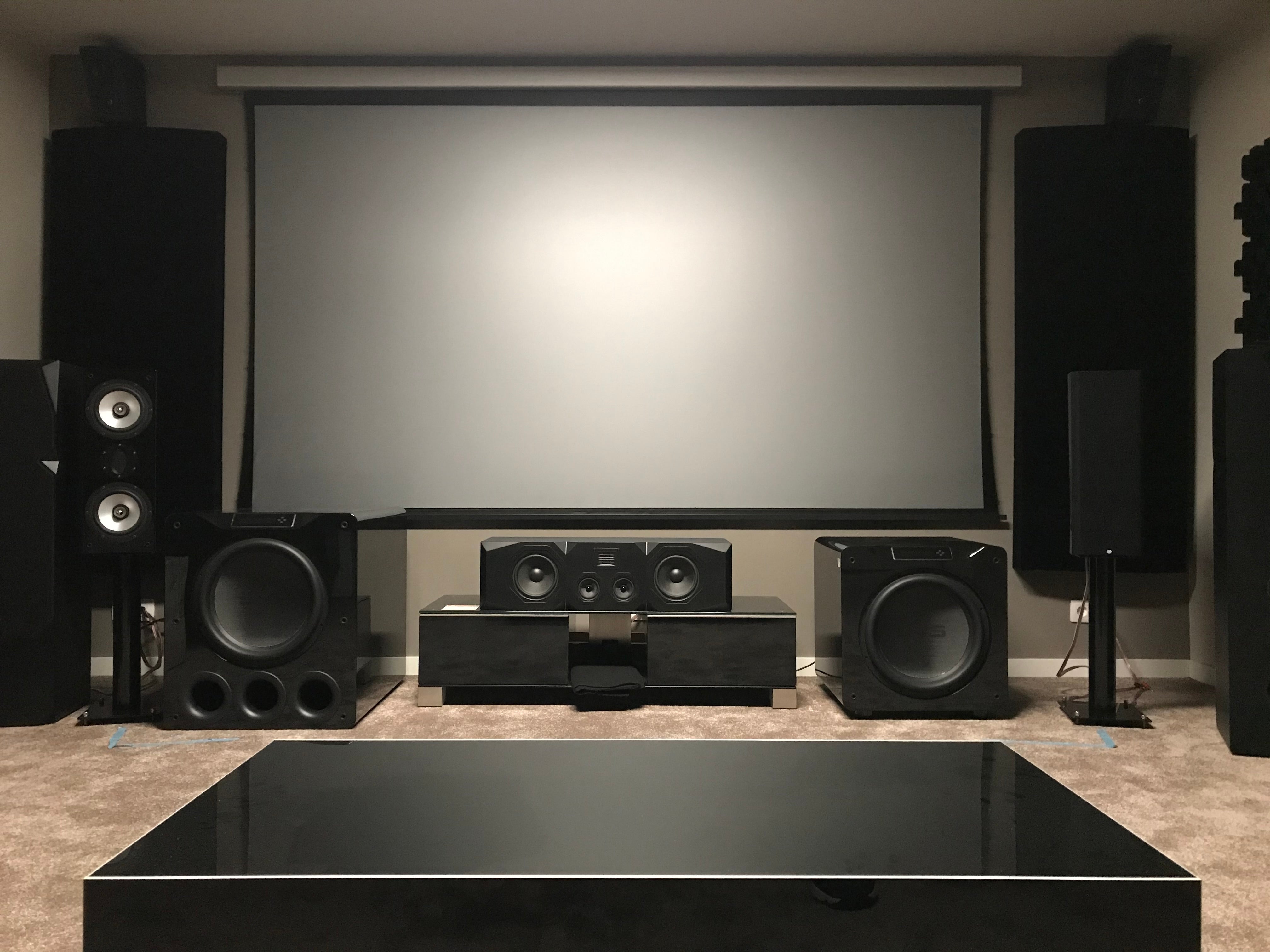
2. Hardware Configuration
Subwoofer placement is driven by the number of subwoofers in your system, listening room configuration and aesthetics. In general, spatial diversity is preferred.
Test Signal Connection
You’ll need to connect the audio output from the computer to your miniDSP. Room EQ Wizard (REW) test signals generated in your computer will be sent to the miniDSP via USB. The direct USB connection approach is ideal as we are calibrating the subwoofers as a single virtual subwoofer and then later connecting the miniDSP to the AVR via analog cables.
Be sure that all of your subwoofer cables are of good quality, adequate length and securely connected. We recommend using USB revision 2.0 cables.

3. Nominal Subwoofer Settings
At this time you can check that the built-in level, equalization, inversion and crossover frequencies of the subwoofers are either bypassed or set to nominal. Your subwoofers should be set as below, so as to not interfere with the crossover, gain and delay parameters that will be set up in the miniDSP Device Console.

4. Subwoofer Placement
Generally, subwoofers can be placed against the front wall near the front left and right main speakers. The front left and right main speakers can be pulled out for imaging purposes.
Before proceeding with tuning, it's a good idea to experiment with various subwoofer positions and orientations depending on aesthetics and room limitations. Use REW to see the effects of the changes in position. Regardless of where the subwoofers end up, their location can be compensated for in a multi-subwoofer system by adjusting the equalization and relative delays.
5. Subwoofer Routing
Your subwoofers can be driven monaurally, as left and right, or as a combination of monaural center, left and right. Typically input channel 1 is used for the left, and 2 is used for the right channel. The routing matrix also allows you to adjust relative channel levels.
Monaural Three Subwoofer System
If your AVR only has a single subwoofer output, then your configuration will be monaural. In this example, we show three subwoofers that could be front left, front right and a center rear. This also can apply to two or four subwoofers.

Quad Left and Right Subwoofer Setup
If your AVR has left and right independent (stereo) outputs for the subwoofers, then you can configure them as such. In this example, we show front left and right subwoofers plus rear left and right subwoofers.

Left and Right Stereo Subwoofers with a Third Monaural Subwoofer
This example is for an AVR with independent left and right subwoofer outputs. This could be left and right front subwoofers with a monaural center rear subwoofer.

Left and Right Subwoofers and Two Rows of Bass Shakers
Here we show a routing matrix with left and right stereo subwoofers and two rows of actively driven bass shakers or ButtKickers. You gain several advantages by using a miniDSP for base shaker integration. First, you can use standard high power amplifiers. Second, you have the convenience of the Device Console configuration platform. See compatible crossover in next section.

6. Crossover Settings
Setting of the optimal crossover frequencies is critical to achieving the best overall system performance. Here are the things you need to remember:
- Depending on the size of your main speakers, determine the frequency and slope of the high pass filter your AVR will be applying to your main speakers.
- You can choose a matching low pass frequency and slope for your subwoofers and then later experiment with different slopes and overlapping or underlapping frequencies.
- We recommend adding a 10 Hz or greater high pass filter to the subwoofers to eliminate unnecessary driver excursion and load on the amplifiers.
Subwoofers with Differing Frequency Range Capabilities
If your subwoofers have differing frequency response capabilities, you can set high and low pass filters (as shown below) that will focus amplifier power to their useful frequency range. In this example, the subwoofer filter in gray was chosen for a corner horn speaker that did not have useful frequency response below 40 Hz.

Bass Shakers and Left / Right Subwoofers
Bass shakers or ButtKickers can add a lot of intensity to your home theater experience. You can use standard high power amplifiers and set all of the frequency ranges, amplitudes and delays with miniDSP Device Console. In this example, we have chosen a frequency range of 10 to 35 Hz. This applies power to the useful range of the shakers and also eliminates annoying audible output above 35 Hz.

7. Validating Subwoofer Polarity
You’ll need to confirm that the subwoofers are in phase with each other and in phase with the rest of the home theater speakers. This ensures that you will get the most accurate and highest power output across the frequency range.
Confirming Multiple Subwoofers are in Phase
First, the left and right subwoofers are measured individually (red and green). Next, the left and right subwoofers are measured simultaneously (blue), showing 6dB of gain when summed. If they are out of phase, they will be subtractive.

Confirming Subwoofers are in Phase with Full Range Speakers
We can now verify that the subwoofers are in phase with the full range speakers. If you have an inverted phase situation, the level will subtract in the crossover region of the drivers. The goal is to end up with all of the speakers being additive in power level.

8. Delay Settings Using Physical Measurement Method
The time of arrival of subwoofer signals needs to be equivalent so they will be additive in power at the main listening area. Using physical measurements for determining the delay offsets from the various subwoofers to the listening position requires the subwoofers to be the same design and have equivalent near-field latency and phase.
From Device Console, enter the individual subwoofer delay settings as follows:
- Measure the distance of the subwoofers from the main listening area
- Calculate the difference in distance of each subwoofer from the farthest subwoofer in feet
- Find the delay in milliseconds by dividing the distance in feet by 1.11
- Enter the resulting value in the delay section for each respective channel (1.11 ms = 1 ft)


You also can make delay calculations using the electronic method with REW. See our tech blog on Using Delay Settings to Integrate your Audio System
9. Creating and Loading Correction Filters with REW
Here we will apply an REW room correction filter to a Device Console PEQ bank. You can observe the before (blue) and after (red) frequency response of one subwoofer.

Each subwoofer can be calibrated independently by making a sweep and then going to the EQ page of REW to generate the correction filter. REW calculates the biquadratic filter coefficients, which you then download into the PEQ menu on Device Console. For details on how to perform this correction, refer to the REW V5.20 Help Guide

10. Relative Amplitude Settings
Now you can adjust the relative levels of all the subwoofers to be equal at the center of the main listening area.

Use the gain settings to achieve equal subwoofer levels and to set a level that will be compatible with your AV full range speaker.


11. Connecting to your AVR
At this point, the basic setup is complete and your virtual subwoofer is ready to be connected to your AVR. We recommend you perform a full hardware reset on your AVR, and then rerun your system / room correction (Audyssey, ARC, YPAO, Dirac, etc.). This will apply your AVR home theater calibration integrating your precisely calibrated subwoofer group.
12. Tuning to Taste
After you have completed your AVR system / room correction and are satisfied with the results, you can use the Device Console and adjust the PEQs manually for tuning by taste. You also can have up to four tuning curves for different types of movies and music.

Check out the companion video and more on our YouTube Channel
https://www.youtube.com/@deer_creek_audio
If you have questions or would like to discuss in more depth, feel free to give us a call or drop a line.
Share: