Customize and Room Correct Your Audio System or
Home Theater using miniDSP Device Console
Device Console is the graphical user interface compatible with most miniDSP products. In this blog we will focus on the 2x4 and 2x8 architecture found in the 2x4 HD, Flex series and SHD series. We will cover the HT(x) 8x8 architecture in a future blog.
Device Console’s intuitive interface allows you to set the critical parameters of your miniDSP digital signal processor. The end result is a precisely configured and tuned audio and/or subwoofer system.
Contents
- Device Console Main Screen
- General Settings
- Input Panel
- Input Panel with Dirac
- Main Panel
- Parametric Equalization (PEQ) Filters
- Crossovers: High, Low and Band Pass
- Gain, Delay and Mute
- Channel Inversion
- Save as You Go
- Template Mode
1. Device Console Main Screen
When you receive your miniDSP, the first step is to download Device Console from the miniDSP website to either your PC or Mac. When you connect the miniDSP to your computer via USB, Device Console will be your dashboard for configuring the system.

2. General Settings
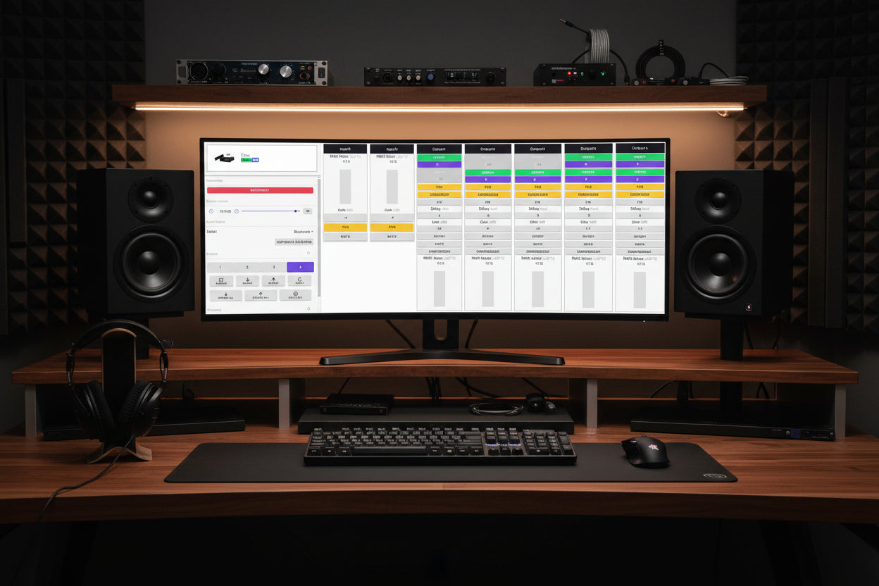
Device Console opens with general settings on the left panel and the configuration controls on the right panel. Using the general settings you can select your input device, adjust master volume, turn Dirac on and off, select and save configuration presets, and refresh your firmware.

There are a number of inputs available, depending on your miniDSP unit. They include TOSLINK, SPDIF, AES-EBU, RCA, XLR and TRS balanced, USB, LAN and Bluetooth.
With Device Console, you have four preset configurations. These store and recall parametric, crossover, delay and other settings, as well as your Dirac projects.
After you've completed a configuration in your selected preset, it will be saved permanently in the miniDSP firmware. You also can export it for backup on your computer.
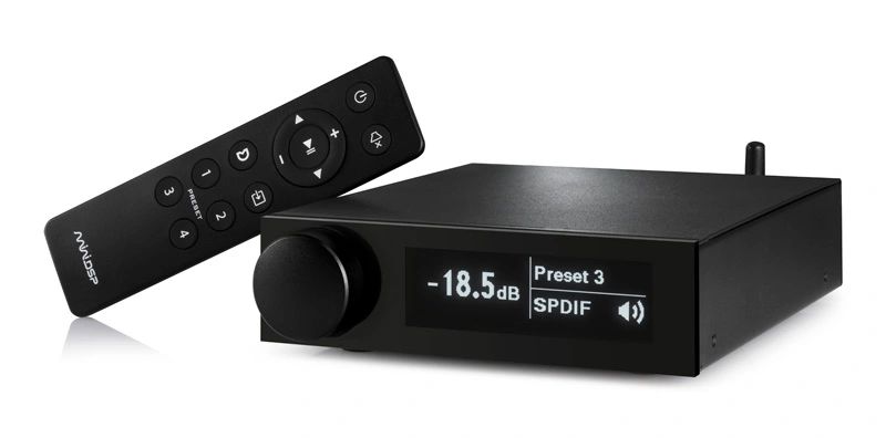
Once you disconnect the USB from the miniDSP, you will be able to control basic functions with the remote control or front panel knob.
3. Input Panel
The input panel in the center of Device Console contains the input gain and PEQ (or Dirac specific) and mute controls. There are two variations based on whether or not your miniDSP is Dirac enabled.
This first variation is for a Flex without Dirac. You can see the RMS meters for inputs one and two, typically left and right. This is where you verify that you have proper input levels and set the gains accordingly.

The PEQ button is located in the input panel and provides access to the 10-band parametric equalizers.

4. Input Panel with Dirac
The input panel of Device Console for a Dirac enabled miniDSP unit contains the correction algorithms created with a Dirac project. These replace the gain, parametric equalization and mute controls. The RMS meters are the same.

5. Main Panel
The main panel of Device Console contains PEQ, crossover, delay, channel gain and inversion controls.
The following example is for a 2.1 stereo system. You can label the routing matrix in accordance with your system setup.

6. Parametric Equalization (PEQ) Filters
With Device Console, you have control of either four or eight input parametric equalizers, depending on your miniDSP model. There are 10 bands you can use independently to adjust frequency, gain, Q and filter type. All parameters can be adjusted in real time and will automatically combine when you add additional filters.
Peak Filters
Peak filters can be used to add gain or loss over wide or narrow frequency ranges, depending on the need. Q is varied to change the width of the filter. The frequency setting controls the center of the filter. An example for using a narrow filter might be to notch out a room resonance or an excessively bright frequency range in a horn.

Low Shelf and High Shelf Filters
A low shelf filter is similar to the classic bass control. You can add gain or loss to the filter. You might want to use a low shelf filter to add mid-range warmth, which would be in the 500 Hertz range. Or to add some very low bass punch, you might start around the 70 Hertz range.
A high shelf filter is similar to the classic treble control. A common application for this might be for speakers that are really bright. You could add a high shelf filter with just a touch of loss, making the speakers more listenable.

7. Crossovers: High, Low and Band Pass
Having full control over your crossover interfaces is a very powerful tuning element. With Device Console you are able to vary crossover frequency, slope and type. You can choose filters that are very soft or extremely sharp, depending on your listening preferences and room characteristics.
For more on active crossovers, please see our tech blog Crossover Basics Using miniDSP Device Console.
Here we show a classic 2.1 system crossover at 80 Hertz, with a slope of 24dB/oct and a Butterworth filter shape.

8. Gain, Delay and Mute
Gain can be set on each of the four output channels individually. This allows you to match levels between all the speakers in your system and adjust them to taste, such as adding more amplitude to the lower frequencies for a warmer sound.
Delay is for synchronizing the time of arrival of audio from various speakers and subwoofers, bringing signal coherence to the listening area. For more information on this topic, please see our tech blog Using Delay Settings to Integrate your Audio System.
Mute allows you to mute a channel that is not being used. This can be used to isolate the channels you are measuring during system tuning.

9. Channel Inversion
Inverting a channel is the equivalent of reversing the plus and minus leads to a speaker.
In a system with subwoofers or active multi-way speakers, the relative polarity of all speakers should be the same. Low frequency speakers are especially sensitive to polarity inversions that can cause a loss of bass output.
It's easy to determine if speakers are out of phase. Simply measure the speakers independently and then measure the left and right channels together to be sure they are in phase. You can see in this example they add by 6 dB, meaning they are in phase.

You also should verify your subwoofers are non-inverted from the main speakers. If you have an inverted phase situation, the level will subtract in the crossover region of the drivers. The goal is to end up with all of the speakers being additive in power level.

10. Save as You Go
As you continue to explore Device Console and use its features to fine tune your system, be sure to save your configurations so that you can recall them another day.
11. Template Mode
Template mode is a great way to experiment with Device Console before you purchase a miniDSP unit. You can explore using Device Console with different miniDSP models, create various configurations and then save them to upload later.
If you would like a free Device Console license, please give us a call at Deer Creek Audio.

Check out the companion video and more on our YouTube Channel
https://www.youtube.com/@deer_creek_audio
If you have questions or would like to discuss in more depth, feel free to give us a call or drop a line.
Share: