Setting up miniDSP Flex HTx in your Home Theater or
Multi-way Active Stereo System
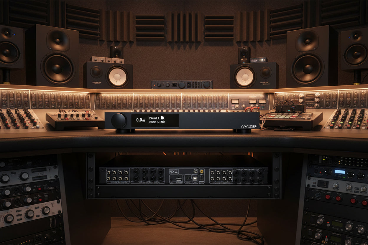
The miniDSP Flex HTx is a digital signal processor for both home theater and multichannel audio systems. Device Console is the user interface that allows you to set the audio system parameters of your miniDSP digital signal processor.
In this blog we’ll cover the 8 x 8 architecture used with the Flex HT and HTx. Our focus will be on the Flex HTx, followed by examples of a home theater setup and a 4-way active system.
The Flex HTx features a variety of controls for inputs, bass management, parametric equalization (PEQ), optional Dirac, configurable crossovers, channel mixing, splitting and output routing.
This functional block diagram shows all of the setup features that are configurable using Device Console.

Contents
- Flex HTx Overview
- General Settings
- Configuration Controls
- Input Channels
- Bass Management
- Channel Routing
- Dirac / Parametric Equalization (PEQ)
- Matrix Mixer
- Output Channels
- HDMI (ARC)
- Signal Flow Diagram
- System Spotlight: 5.2 Home Theater TV System
- Signal Flow Diagram
- Input Channels
- Bass Management
- Channel Routing
- Dirac / PEQ
- Matrix Mixer
- Output Channels
- HDMI (ARC)
- System Spotlight: 4-Way Active System with Subwoofers
- Signal Flow Diagram
- Channel Routing
- Dirac / PEQ
- Matrix Mixer
- Output Channels
- Matrix Mixer
- Output Channels
- Completing your Setup with an Optional Dirac Project
1. Flex HTx Overview
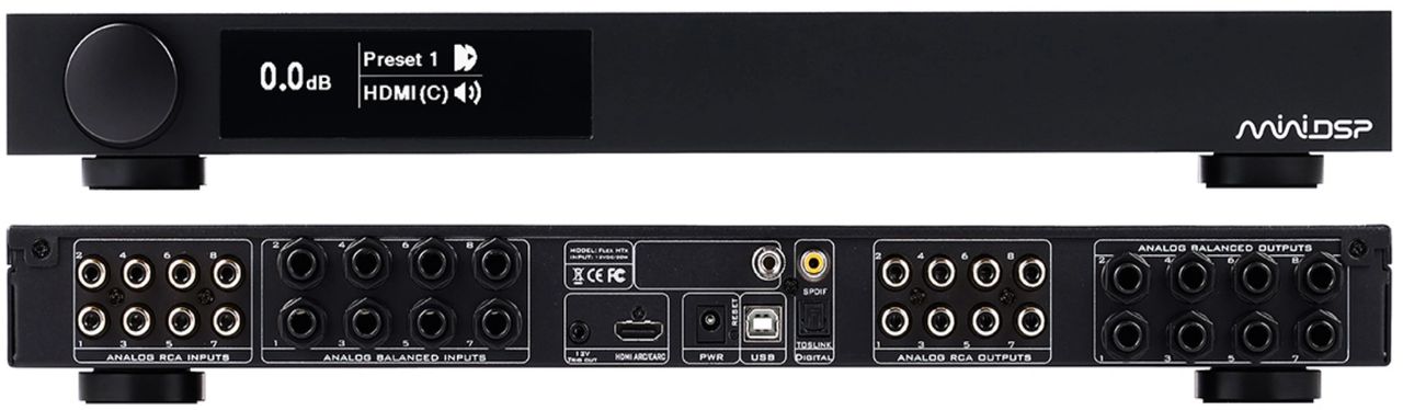
The miniDSP Flex HTx is an eight-channel input, eight-channel output, high-resolution audio processor. It features analog RCA and TRS (balanced), multichannel USB audio, eight-channel linear PCM, HDMI eARC, SPDIF and TOSLINK digital inputs.
When you receive your Flex HTx, you’ll download Device Console from the miniDSP website to either your PC or Mac. Once downloaded, Device Console will be your dashboard for configuring the system.

2. General Settings
Device Console opens with general settings on the left panel and the configuration controls on the right panel. Using the general settings you can adjust master volume, turn Dirac on and off, and select input channels. You also can select, save and recall configuration presets, perform reset all and refresh firmware.

Diagram 3. General settings are found on the left panel of the Device Console dashboard
The tabs along the top of the Device Console dashboard provide access to the configuration controls, with each tab opening to a specific page.

3a. Input Channels
The Input Channels page allows you to label each of the input channels. You also will use this page to observe input levels coming from each of your source channels.
Please note: In the following image the input channels are labeled with the standard HDMI 7.1 nomenclature. These can be labeled to accommodate any of the various HTx applications.

3b. Bass Management
The Bass Management page is used to determine from which input channels you wish to extract LFE low frequency and subwoofer information. This is then combined into the bass management channel and can be routed to one or multiple subwoofers.
You can set high and low pass filters for all signals as they pass through or are routed to the bass management channel, and also set the relative amplitude levels of each input channel as it passes through this matrix. Please note, it is common that the LFE channel requires an additional 10 dB of gain to be added.

3c. Channel Routing
The routing matrix allows channel mixing, splitting and output routing, as well as relative level setting. You can mix, split and route channels prior to Dirac / PEQ processing.

3d. Dirac / Parametric Equalization (PEQ)
Dirac is an optional feature of the Flex HTx, and when enabled applies multichannel room correction. A Dirac project is initiated from general settings on the Device Console dashboard.

The Dirac / PEQ page also provides a full function 10-band PEQ, which can be used in addition to or in lieu of Dirac. The parametric equalizer allows you to adjust frequency, gain, Q and filter type individually. All PEQ parameters can be adjusted in real time.

3e. Matrix Mixer
The matrix mixer is used for any final routing, mixing or splitting prior to the Output Channels page.

3f. Output Channels
The Output Channels page contains all of the primary controls that can be applied on each output channel individually:
- PEQ
- Crossovers
- Delay
- Gain
- Invert
- Mute
- Compressor

Each of the eight output channels has a column of controls for input, PEQ, crossover, delay, gain, invert, mute, compressor and level meter.

3g. HDMI (ARC)
The HDMI (ARC) page provides information about the eARC connection. Here you can verify what your TV is sending to the Flex HTx, whether it be 2 or 7.1 channel linear PCM.
3h. Signal Flow Diagram
The Signal Flow Diagram is designed to work as a roadmap, allowing you to chart the different elements of your system before beginning to set the configurations.
This example shows a straight-through configuration with no bass management or crossovers, and is the default configuration for the Flex HTx. It shows the standard HDMI eARC channel assignment for 7.1 on the inputs, then goes straight through all of the routing and digital signal processing functions and on to the outputs.
If you have Dirac enabled on your Flex HTx, you’ll decide how Dirac processing is applied to either individual or groups of channels.
You can download a blank Signal Flow Diagram worksheet here and use it to sketch ideas for your system layout.

4. System Spotlight: 5.2 Home Theater TV Setup
In this example, we will explore a TV-centric 5.2 home theater system. The system has an Apple TV media streamer and an LG OLED TV with HDMI eARC. The eARC feature provides 7.1 channel linear PCM from the TV to the Flex HTx.
The HDMI eARC feature enables simple integration into modern home theater systems. A single connection to an eARC-enabled television allows 2 or 7.1 channel linear PCM audio from any sources connected to the TV.
The system block diagram below shows a TV-centric 5.2 home theater system. The signals are coming into the Flex HTx via HDMI eARC from the TV. The final output represents the signals being sent to the subwoofers, power amplifiers and speakers.

4a. Signal Flow Diagram
In the Signal Flow Diagram, we’ve routed the 7.1 inputs to be compatible with our 5.2 home theater setup. Note that in the Bass Management section we have channel routing along with high and low pass filters. All of the splitting, filtering and mixing is performed prior to the Dirac / PEQ page, so any Dirac or PEQ room correction will occur as the final step.

4b. Input Channels
The default labeling here is the standard convention for HDMI 7.1 channel linear PCM. This represents the signals coming into the Flex HTx via HDMI eARC from the TV.

4c. Bass Management
The Bass Management page is critical to our 5.2 home theater system. This is where we define which signals are routed to the subwoofers, and where the high and low pass crossovers are set.
You can see the graphical implementation in the Signal Flow Diagram (diagram 14 above).

4d. Channel Routing
On the Channel Routing page we are mixing the default 7.1 channels coming in over HDMI eARC to match the requirements of our 5.2 system.
We are combining the four surround and rear channels into two rear surround speakers. We also split the bass management channel to actively drive our two subwoofers.
You can see the graphical implementation in the Signal Flow Diagram (diagram 14 above).

4e. Dirac / PEQ
For a home theater setup, Dirac is performed on each of the 5.2 output channels. A Dirac project is initiated from the Device Console general settings and is a separate, optional application.
In addition to or in lieu of Dirac, you also can use the 10-band full function PEQ to adjust frequency, gain, Q and filter type individually. All the parameters can be adjusted in real time.
For more details on how to complete a Dirac project, please refer to the miniDSP Flex HTx user manual: Dirac Live - miniDSP Flex HTx User Manual
4f. Matrix Mixer
The matrix mixer allows you to do final routing and mixing after Dirac or PEQ processing and prior to the Output Channels page. In this example, it's a straight through with one exception. The third input is not used as the LFE channel was routed to the bass management.

4g. Output Channels
The Output Channels page shows the signals we are sending to the power amplifiers and subwoofers to drive our actual hardware speaker and subwoofer configuration.
Here we set individual channel levels to ensure the system has a good, balanced sound with clear voices and tight powerful bass. In this system, we have applied the following primary controls on each output channel:
- Crossover
- Delay
- Gain
- Invert

4h. HDMI (ARC)
The HDMI (ARC) page allows you to verify that your TV is sending 7.1 channel linear PCM to the Flex HTx and that it is being properly received.
5. System Spotlight: 4-Way Active System with Subwoofers
In this system spotlight we are using a Flex HTx in an active 3-way speaker system that includes stereo subwoofers. This is a true active 4-way stereo design.

5a. Signal Flow Diagram
The Signal Flow Diagram for this example shows a 2-channel stereo input, which is then divided into four active channels for each of the Left and Right speaker groups. Using the active Output Channels page, we optimize the crossovers, delays, gains and polarities.

5b. Channel Routing
The Channel Routing page directs the Left and Right inputs into the Dirac / PEQ processing section. In this example, the system is finally calibrated using either a Dirac project or PEQ equalization after the eight output channels have been configured.

5c. Dirac / PEQ
The overall stereo system can be calibrated using either Dirac or PEQ with REW corrections. This step is completed after all of the output gains, crossovers and equalizations have been finalized. The result will be an integrated room corrected system.
For more details on how to complete a Dirac project, please refer to the miniDSP Flex HTx user manual: Dirac Live - miniDSP Flex HTx User Manual
5d. Matrix Mixer
Next, the matrix mixer separates the main left and right inputs into the four active output channels per stereo side, for a total of eight. After this separation the crossovers, delays, gains and polarities need to be optimized using the Output Channels page.

5e. Output Channels
In this system, we applied the following primary controls on each output channel:
- PEQ
- Crossovers
- Delay
- Gain
- Invert
The goal here is to configure and optimize your active 4-way system using the above controls. With REW you’ll observe the overall system frequency response and confirm the results by listening evaluation.

This plot shows what a typical active 4-way crossover looks like in the output channels PEQ. For more information on setting up the active crossover system, please see blog Crossover Basics using miniDSP Device Console.

6. Completing your Setup with an Optional Dirac Project
For more details on how to complete a Dirac project with your Flex HTx, please refer to the Dirac Live - miniDSP Flex HTx User Manual
Check out the companion video and more on our YouTube Channel
https://www.youtube.com/@deer_creek_audio
If you have questions or would like to discuss in more depth, feel free to give us a call or drop a line.
Share: